 |
| SCRATCH-BUILDING A
CARRIER IN 1:1200 SCALE IJNS SHINANO, 1945 By John Youngerman |
|
| SCRATCH-BUILDING A
CARRIER IN 1:1200 SCALE IJNS SHINANO, 1945 By John Youngerman |
BACKGROUND This article complements an earlier article on
scratch-building a battleship, specifically USS
Arkansas (Click
for Arkansas article) in late-war
configuration. Interest had been expressed in techniques for scratch-building an
aircraft carrier. Aircraft carriers are by their specialized nature
fundamentally different from surface warfare ships and one needs to use somewhat
different techniques in building them. For some years, I have been intending to add
IJNS Shinano to my fleet of Japanese WW2 carriers, but had been
somewhat daunted by its layout and the lack of really good reference material.
However, the appearance of the Hasegawa 1:700 scale kit of Shinano made the job relatively easy—at least as far as research goes. While I
recognize that almost none of the known references on Shinano agree totally in layout details—or even in total length—I believe that one
may rely on the research performed by the design staff at Hasegawa. I
therefore have used their kit as a [hopefully] reliable basis for building my
own model in 1:1200 scale. Dimensions taken from the kit were multiplied by
0.5833 to get the corresponding dimensions in 1:1200 scale.
GENERAL PROCEDURE
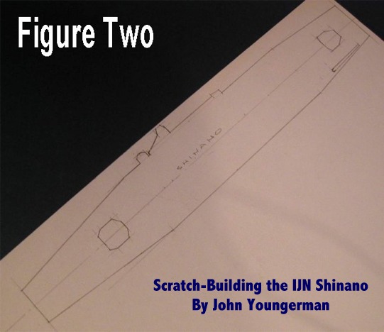
The first work item is to lay out the carrier deck. Figures One and Two show the deck as laid out on 3-ply Bristol Board (BB). With a
deck this size and with the overhangs at bow and stern, the extra strength of
3-ply BB over 2-ply BB warranted use of the thicker material. The deck shape is
then cut out using a sharp #11 blade and a straight edge and the edges sanded to
final shape. With carriers, it is a good idea to lay out and cut out the deck
first, as the entire model has to fit that shape. With U.S. carriers, I usually
use 2-ply BB for the "gallery deck" and include all the galleries. I
then glue on top of that the actual carrier deck using 1/16" balsa,
finishing with one-ply BB. I add the screens to the galleries using 1-ply BB or
card stock and that part is essentially done, except for weapons. On the other
hand, Japanese carriers typically did not have galleries, but used "sponsons"
attached to the hull and braced for weapons and other items. Shinano is typical of this design method. Now, with the deck cut out, let’s go to the
hull. Here’s where it gets difficult!
| Click to Enlarge Figures One & Two |
|
 |
|
THE HULL
As is well known, Shinano was hull #3 of the Yamato class of
super battleships. It was converted before completion to a huge aircraft carrier
with two separate hangars—a forward hanger for its own complement of aircraft
and a stern hangar for maintenance, refueling, and repair of aircraft from other
carriers. The design of the model reflects the separate hangars. I made an early
decision to leave open the forward hangar area rather than building it
"solid". Hangar sides were constructed of 3-ply BB with interior
structures of balsa which were used to brace the BB sides. The Hasegawa kit was used as a guide here. The hull itself was made of ¼" balsa plus
2-ply BB for the hangar deck. It was necessary to do some cutting for the stern
and bow areas and to add 1/16" balsa plus cardstock for the deck at the
bow. The balsa was sanded to a sloping shape to reflect the sheer rising to the
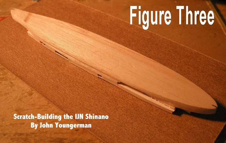
bow. Figure Three shows the hull assembled and roughly cut to shape and
being sanded flat on top to accept the carrier deck. The hull at the hangar deck
level is essentially the same width as the hull at the bulges. It is necessary
to tape off the bulges and then cut and sand the hull to shape. The bow and
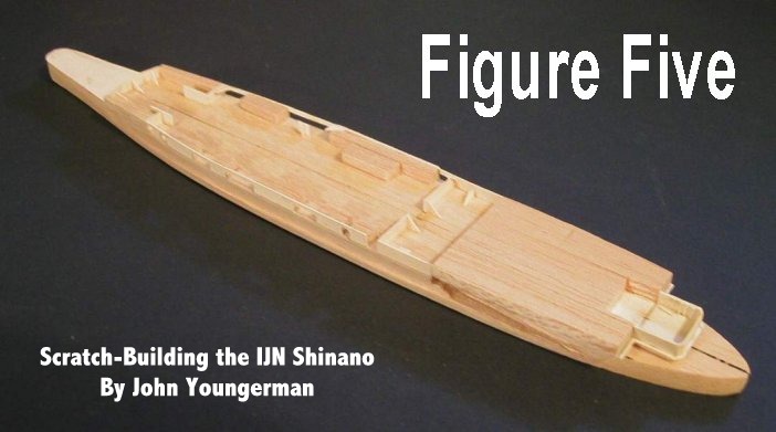
stern shapes are cut and sanded in at this point, as shown in Figures Four and Five. The bow flare is roughly cut to shape using a sharp razor blade
and finished with sandpaper around a dowel. Get yourself a selection of
different diameter dowels and cut to about 6" in length. They are very
handy for shaping the bows of ship models in this scale. When I have
occasionally had a ship with a very gentle flare, I have used a paint bottle to
wrap the sandpaper around. It’s kind of awkward, but it works. The aft
elevator was built into the hull and detailed inside (a waste of time) as I
intended to show the aft elevator lowered (see Figures Thirteen and Fourteen).
The gallery around the aft elevator is made of cardstock, which forms the
"floor" of the elevator well. At this point, you have a completed
hull, open aft elevator well, open forward hanger, and carrier deck--all ready
to accept paint. As recommended by Hasegawa, I used German Grey-Violet
for the hangar, aft elevator well, and edges of the carrier deck. The open bow
and stern areas were painted with Colourcoats IJN Type 21 Camouflage
color—a rather sickly light gray-green. I might mention here that the capstans
for the anchor chains were added from 0.035" and 0.060" plastic rod—the
Shinano had battleship-sized
anchoring gear—and the anchor chains were made from lintless thread glued to
the deck and wrapped around the capstans. Anchors were built very simply from
0.015" plastic sheet with a 0.010" x 0.020" bar glued to the
bottom. The finished anchors were then glued to the bow using CA-glue.
Throughout the building of this model, I used white glue to glue paper or balsa,
but used CA-glue to glue plastic to paper or balsa. Plastic parts were glued to
each other with either liquid MEK or tube glue.
| Click to Enlarge Figures Three, Four & Five |
||
 |
 |
|
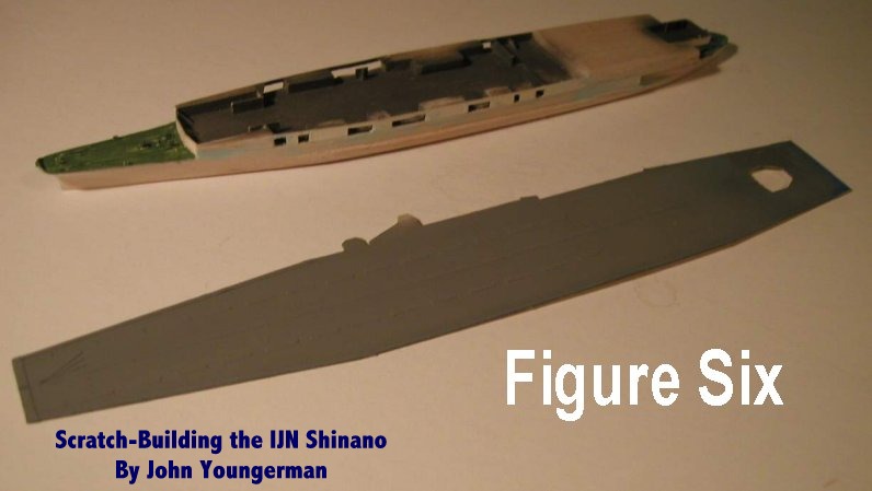
PAINTING THE DECK
The main deck color was British Dark Sea Grey, lightened slightly
with white. Supposedly, the deck was a cement substance rather then wood planks.
The edges of the deck were masked to preserve the Grey-Violet color and the rear
landing area was painted white as were the areas of the stripes. One can use
decals for the stripes—and they work quite well—but maintaining a straight
line with decals, especially for broken stripes, is quite difficult. I chose
instead to use masking tape strips. The red stripes at the stern are decals.
Again, one could mask and paint them. Figure Six shows the hull with
hangar deck painted and the carrier deck masked and painted.
 |
THE SPONSONS
Building the sponsons on Japanese carriers is perhaps the most
difficult task. In general, sponson shapes are irregular and involve lots of
careful measuring, cutting, and gluing of screens and support structures
underneath. I used the Hasegawa kit as a guide in laying out my sponsons
on 2-ply BB. I glued 1-ply BB screens to the edges (screens are made from
0.005" strips cut from the 1-ply sheet. I am aware that many screens,
especially on Japanese ships, were less than five feet high, but long experience
has convinced me that using 0.003-0.004" strips for the screens just doesn’t
look right. Note that the undersides of the sponsons have a support structure
that must be constructed. Basically one can make this from a central piece of
0.040"-0.050" plastic rod cut about 0.02"-0.03" long to form
a "disk" which is glued to the underside of the sponson with CA-glue.
Make small triangular support shapes radiating out from the central disk from
cardstock and glue them onto the underside. Figure Seven shows the port
side of the hull with the deck glued to the hull and sponsons added and braced.
Braces were made from 0.02" plastic rod cut to length. Figure Eight similarly shows the starboard side. Figure Nine shows the port sponson
structure viewed from below. Figure Ten similarly shows the starboard
sponson structure. At this point, one is ready to add the weaponry.
| Click to Enlarge Figures Seven, Eight, Nine & Ten |
|||
THE WEAPONRY
The armament of Shinano consisted of 5" twin AA guns in eight standard shields plus a host of
triple 25mm AA guns and twelve multiple AA Rocket launchers at bow and stern.
There are several ways to make the 5" shields—use one piece cut to shape
with a razor blade, which was the method I used, or make them from three
separate pieces glued together. I used balsa strip, but plastic shapes could
also be used. The guns are 0.008" brass wire glued to the shield structure
with white glue. The triple 25mm are a very basic shape cut to length from balsa
and glued to the sponson. The guns were cut from 0.003" steel wire. If you
don’t have any wire this small, you can use 0.006" brass wire, but it
will look just a bit "hefty". You may be able to find very fine wire
in some of the electronic gadgets you have sitting around that don’t work
anymore. The rocket launchers were made from plastic strip shapes glued to a
plastic base.
THE ISLAND AND FINISHING THE MODEL
The island was constructed separately (usually a good idea for
carriers) layer by layer. Each layer represents a deck and is generally
constructed from 1/16" balsa with 2-ply BB glued on top. This produces a
shape that is about 0.085" high, which is just about right for deck
heights. The funnel was shaped from a piece of 1/8" balsa with the cap made
from cardstock bent to shape and glued, then sanded to proper shape. There are
11 funnel pipes, which were made from 0.020" plastic rod cut to length and
bent to shape. The funnel pipes are held in a rather unique support structure
which was made from 0.020" x 0.030" and 0.020" square plastic
strip. This structure was glued to the funnel and island using CA-glue and the
funnel pipes inserted and glued into place using MEK. The radar screens were
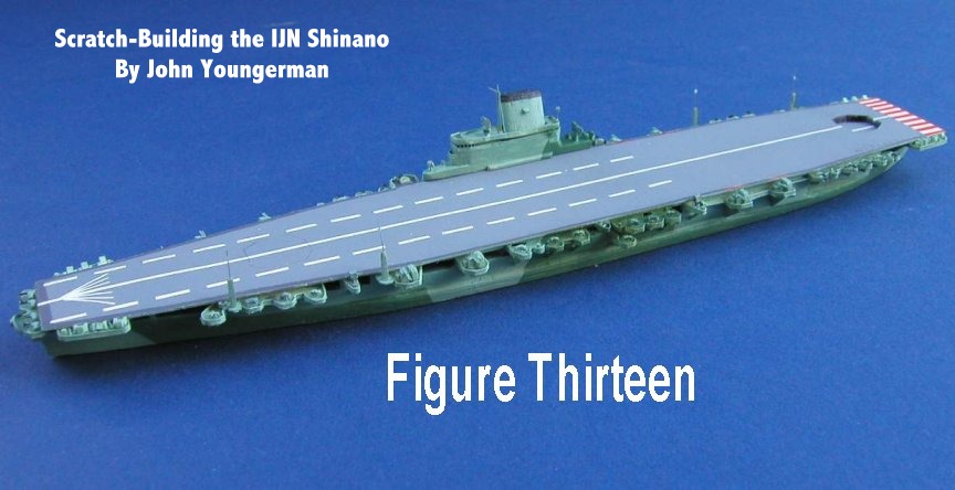
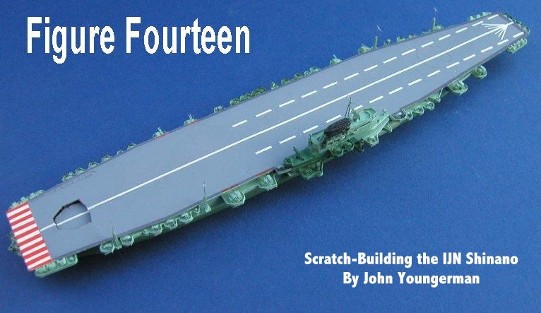
made from photo-etched brass screening, folded over. Figure Eleven shows
the completed and painted hull/deck/sponsons with the as yet unpainted island
from the port side. The deck masking has been removed and the red stripe decals
applied. Figure Twelve shows the same view from the starboard side. The
hull was spray painted IJN Type 21, then masked, and IJN Type 2 (the darker
green) sprayed on. Note that hand painting is very acceptable. Don’t forget to
paint the chrysanthemum emblem at the bow gold. The anchors and chains are
metallic gray. Figures Thirteen and Fourteen show the completed
model from port and starboard. I realize that this has been a very short
description of my methods, but using this general procedure would enable one to
build any of the imperial Japanese carriers.
| Click to Enlarge Figures Eleven, Twelve, Thirteen & Fourteen |
|||
 |
 |
||
John
Youngerman's Web Site |
_____________________________________________________________________________________________
|