| Click to Enlarge |
|
|
Scratch-Building USS Arkansas In 1:1200 Scale |
Scratch-building ships in 1:1200 scale is a very exciting and challenging hobby. I have been pursuing this hobby for about 40 years and still enjoy the ever changing challenges. Over the years, my techniques have changed—and hopefully improved—and the materials available to me have vastly improved and expanded. In addition, there are now photo-etched (PE) parts available in 1:1200 scale, including both railings and USN radars. They are NOT easy to use, requiring what seems like infinite patience and extreme delicacy to get the correct results, but using them can help the visual impact of your finished product a great deal.
The purpose of this article is to provide 1:1200 and 1:1250 collectors and modelers with a "how to" from my perspective, using the materials and tools I have found best over the years. I recognize that there are several mediums in which one can model ships in this scale and there are modelers who are advocates for each of these mediums—balsa, pine, basswood, plastic, etc. My personal approach is definitely "multi-media", but I have always used that "impossible material"—balsa wood—for hulls, turrets, and deckhouses. Therefore, let’s go through the construction of an elderly U.S. battleship during the latter part of World War II. Battleships have lots of different size guns on them and the older ones have some interesting and funky design features. I chose USS Arkansas (BB33), commissioned Sept. 11, 1912 before WW I and still serving in 1945 (she was sunk at Bikini Atoll on July 25, 1946). By 1945, she had been refitted and updated several times during the war years, but her appearance was essentially unchanged from the 1930s. More guns, radar, etc., but she still looked like a member of the pre-WW II "battle line". One of the reasons I chose this particular ship is that it has a number of different size and function guns and some unusual hull features.
REFERENCES
DIMENSIONS OF MODEL
Arkansas was about 562 ft. o.a.
in length, although I was unable to get my sources to agree. I went with the
number in reference 1, giving a model length of 5.62" in 1:1200 scale. Beam
was stated as 93.16 ft., giving a model width of 0.93". The beam over the
blisters was given as 106 ft., giving an overall width of 1.06". Noting
that 106 – 93 = 13, I determined that each blister was 0.065" thick. This
is precisely the thickness of 1/16" balsa sheet, making construction of the
blisters much easier (they were actually not very easy at all due to their
elaborate shape). One of the strangest features of Arkansas was its unique slanted deck. References 1 and 3 agree on a main deck height at
the bow of about 27 ft. = 0.27" and a height of 20 ft. = 0.20" at the
stern. The deck slants continuously.
MODELING THE HULL
The first thing to do is to draw the deck plan on 2-ply
"polished finish" artists’ Bristol Board, which is available from
most good art stores. See Figure One. In the photo, the deck shape has been cut
out with a sharp #11 blade. Note that I chose to include the "sponsons"
for the 6"/51 cal. secondary armament with the main deck rather than try to
add them later. Both methods are valid; it was just a choice prompted by
experience. Figure Two shows the deck plan glued (using a "glue stick"
rather than white glue to avoid hull warping) to a plank of balsa which had been
shaped in profile to match the slant of the main deck. This was done by using a
sanding stick after removing a certain amount of material using a razor blade. I
highly recommend making sanding sticks by gluing sandpaper to wood
"sticks". As the sandpaper becomes "used", peel it off and
glue on fresh paper.
| Click to Enlarge |
|
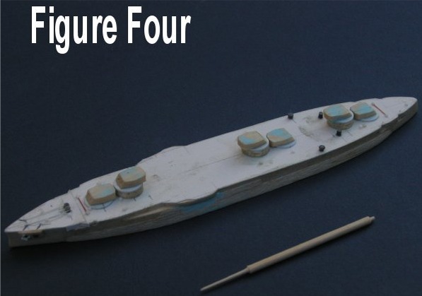
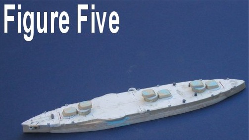
Figure Three shows the appearance of the hull after cutting and sanding to shape, but before adding the blisters and shaping the bow. One of the noteworthy and very handy features of Bristol Board is that you can sand the edges without "mushing" them out of shape. This allowed me to sand both the balsa and the BB to the proper shape. The hull is marked for locating the six turret barbettes and the hawsepipes. At this point, the bow flare (not very pronounced in this ship) was sanded using a ½" diameter wood dowel with sandpaper wrapped around it. This is an area that requires some artistry and a "sense" of what the bow shape is. I go over and over the area with light strokes to achieve the shape I want. Note the unusual "bulge" over the port side hawsepipes. Make from 1/32" balsa sanded to shape. Now the blisters were measured off the profile view and cut to rough size from 1/16" balsa sheet. They were then sanded to proper shape and trial fitted to the hull. They were curved to fit the hull by gently rolling a ½" dowel over them as they lay against my finger. Then they were glued on with white glue. At this point, I added the six turret barbettes and most of the deck features, including the anchors and ventilators, etc. The barbettes were made by cutting out and sanding to circular shape 0.020" plastic and CA-gluing the plastic circles to balsa for the super-firing turrets. Of course, if you are lucky and find that the barbettes are just the right diameter, you could use Evergreen tubing. I recommend sawing the tubing rather than trying to cut it with a blade as you will get more accurate results. All of the deck features were made from plastic shapes commercially available from Evergreen and TechStar. The anchors are cut out of 0.015" sheet plastic with 0.010" x 0.020" crossbars glued on. Simple, yet effective. I use "lintless" thread to simulate anchor chains. Perhaps someone will make them in PE someday. Be tedious, though, twisting every other link… Figures Four and Five show the finished hull with several coats of clear lacquer on it. The blue is 3M’s Auto Body Glazing Putty which I apply over holes and noticeable wood grain. It’s very good, but terribly expensive—another brand would probably do as well. Some final light sanding will still be necessary to ensure it is smooth. Note the toothpick next to the hull in Figure Four with an 11" gun sanded to a tapered shape using a sanding stick. The guns can be added at any time. Figure Five shows the hull after adding the shields for the 40mm quad mounts; these were cut from 3/16" Evergreen tubing. Ream out the tubing using a #11 blade before removing the shield piece from the tubing. Use a saw to remove the shielding and finish reaming out the inside with a circular file. You want the shield to be very thin, yet strong enough not to warp out of shape or break as you handle it and position it on the deck. Additional deck details have been added, such as bollards, which are 0.020" rod glued to 0.010 x 0.020" strip. Ventilators and hatches are made from plastic rod or strip. We are now ready to tackle the superstructure.
| Click to Enlarge |
||
 |
 |
 |
THE MAIN SUPERSTRUCTURE
My normal procedure is to draw the shape of the decks for the various levels
on #2 BB, cut them out, and sand the edges to shape, finishing with a light
sanding of the top and bottom to remove any slight feathers of BB. I believe,
based on many many measurements off plans, that deck heights are usually about 8
- 8-1/2 feet regardless of navy. By using #2 BB for the deck and gluing that to
1/16" balsa for the deckhouse, one gets almost exactly 8-1/2 feet or
0.085" to scale. If there are "screens" on the deck edges, they
can be made from single-ply BB (I used to use USGS quad map paper and now
sometimes use good quality card stock for the screens). Screens are cut in
strips about 0.04 – 0.05" wide and they should be glued to the edges of
the deck before gluing the deck to the top of a deckhouse. You can
as an alternative make decks from plastic sheet and use plastic for the screens.
It looks quite good if done well. However, it is very tedious and the plastic is
liable to break if roughly handled. Paper bends or crushes, but doesn’t break
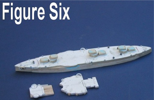
and can be restored to normalcy with a tweezers. Figure Six shows the hull with
the first two superstructure decks lying alongside, unfinished. Note the 40mm
quad mount shields. Figure Seven shows the hull with superstructure decks glued
on and additional deck details such as shields for the after 40mm quad mounts.
These are made from card stock glued directly to the deck as they are irregular
in shape. Shields for the 3"/50s are 5/32" tubing or card stock. Note
that a ninth 40mm quad was, according to references, added to the stern in 1945.
This feature was not seen on the reference plans. Note that the tripod masts are
started also, using 0.030" Evergreen rod for the foremast and 0.025"
rod for the mainmast. Tripod masts with their associated decks are a serious
pain in this small scale. Locating the holes for the two supporting legs
requires delicate measurement or skillful estimation and oversize holes. The
supporting legs will be cut from 0.019" brass rod for strength. Tripods
made entirely from plastic rod tend to be rather flimsy unless one uses large
rod diameters and then they look out of scale and clunky. On the Arkansas, the
large director/spotting room on the foremast tripod is the most difficult to
fit.
| Click to Enlarge |
|
 |
|
The funnel was made from 1/8" Evergreen tubing with the cap shaped from 5/32" tubing using a sanding stick. The funnel pipes are from 0.10" and 0.15" plastic rod. There is a tendency among commercial models to make the funnel pipes as thick as 0.030"—equivalent to a three foot diameter pipe! While I recognize this is because of molding limitations, one should use the correct sizes if scratch-building. Note that the "stump tower" aft of the funnel had been removed by 1945 and replaced with a rather clunky looking two level deckhouse with the second level offset to accommodate the catapult. The catapult was assembled from the PE parts provided by Tom’s Modelworks. It makes a great looking catapult, but the damage to one’s nervous system assembling it can be severe!
The crane towers are very noticeable in this and succeeding classes, and were constructed from 0.060" plastic rod. The 20mm gun positions atop these towers were constructed from 2 ply BB with 1 ply BB shielding. Triangular braces were added to the bottoms of the gun positions. The cranes were cut from plastic sheet with spacers in the plan view. It appears from photos that the cranes were solid in profile view.
A very careful examination of the model and photographs will show that I took a very few "shortcuts" where the effect was minor compared to the amount of work needed to exactly reproduce the original. Also, it became obvious as I went along that the plans in reference 1 are not completely accurate for Arkansas in 1945. I used photographs and text references to make minor changes to the model versus the plans. Incidentally, having very detailed plans such as those in reference 1 are a godsend to the modeler in this and probably larger scales. Their value significantly outweighs the minor errors encountered.
SECONDARY/TERTIARY ARMAMENT
The shields to the casemated 6"/51 cal. secondary guns are among the
largest I have ever seen. Some photos show the casemates as open while others
show the shields in place. I chose the latter and made the circular shields out
of sections of toothpick, sanded to shape/size. Note that the tops of the
shields were slightly "rounded"—an interesting treatment I have not
seen in other ships/navies. The shields were drilled and 0.010" brass wire
inserted for the guns. One could make a case for 0.012" wire, but I tend to
use smaller diameter wire for my guns to avoid any "clunky" look.
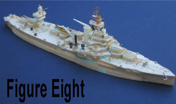
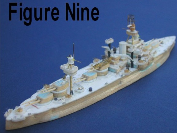
The 3"/50 cal. light AA is very simply made from toothpicks, sanded to a conical shape and cut to size. The gun itself is made from 0.008" brass wire. The nine 40mm quad mountings are made from BB and balsa. The base of the 40mm quad mounting was approximately 14’ x 8’ (0.14" x 0.08") in size and was trapezoidal in shape with cutouts in the longer (forward) edge of the base. Make from two ply BB. Add a turning stand from 3 ply BB and add the gun mechanisms from balsa cut to size, gluing them to the base slightly separated. The guns are made from 0.006" brass wire, mounted two to each "receiver". This calls for good lighting and lots of patience. I recommend white glue as it allows for quite a bit of "fussing" which is generally always needed to make the guns look right. The shields for the 20mm single mounts are made from card stock or could be made from single ply BB (two ply BB looks a bit "heavy" when painted up). Cut a strip of card stock about 0.07" wide (0.06" if you are a stickler for accuracy and want the extra work to make them). Cut the slot in the top for the gun and cut off at about 0.06" in length. Make the "pedestal" from balsa or from toothpick, glue it to the shield, and then to the deck. I have found that the extra work needed to get "fancy" with the pedestal is not rewarded by improved final appearance so I tend to "get simple" with these mountings. For the guns, I use 0.003-0.004" stainless steel wire, which I admit is probably not available to most people. Mine was "liberated" from the aerospace industry by someone and I wound up with it, delighted as you can imagine. Extremely fine copper or brass wire is acceptable, but will bend extraordinarily easily. You could use 0.006" brass wire—your choice, but slightly oversize in this scale. Again, I recommend using white glue to attach the guns. See Figures Eight and Nine for bow and stern views of the finished, but not yet painted model.
| Click to Enlarge |
|
 |
 |
RADAR
I formerly made radar antennas from BB or plastic sheet. Then I found PE
brass or aluminum mesh at my local train shop and have used that in the last
several years for more "realistic" antennas. For Arkansas,
I used the PE radars newly available from Navalis. Truly awesome and
truly nerve-wracking to assemble. Thanks Navalis. Can’t wait for those
funky British or German radars that are sure to come from them. I can’t give
much advise about using the Navalis product, but if you are feeling the
least bit "ham-handed", I suggest trying one of the alternative
methods I mentioned above. Frankly, they look very acceptable. I did not have
much trouble with the large SK radar, but I think that was just beginner’s
luck.
FINISHING THE MODEL
After all the hard work is done, spray the entire model with Testor’s
Glosscote ( I like it better than Dullcote). This was done before taking the
last two photos. It might be appropriate at this point to spray a
"primer" coat of light gray on the model—or use the final color—and
check for imperfections such as holes, scratch marks, wood grain, and roughness.
I always spray the overall color on and mask if necessary for two or three tone
camouflage schemes—unless they are British and those are painted freehand.
Spray the bottom of the model also; it adds a touch and seals the wood. Decks
and such are hand painted using, wherever possible, Acrylic paints. Paul Jacobs
has expounded on the hand brushing qualities of acrylic paints and I agree with
him. However, I hate to spray acrylics as they can turn an expensive airbrush
into a piece of junk. For this model, I used the Colourcoats enamel
paints for both overall color and deck color. I slightly lightened the Navy Blue
with white to suggest weathering and to induce more contrast between the hull
and the decks and thinned it with lacquer thinner for spraying. The decks were
handbrushed using a 3/32" wide "bright" (flat) artist’s brush.
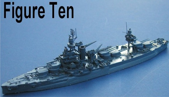
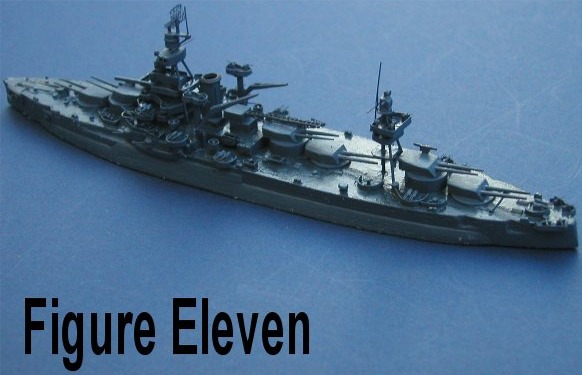
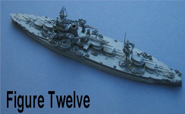
Figures Ten, Eleven, and Twelve finish up the article and show the final
product. Windows came from sticky back clear plastic and were printed on in
several sizes. Find a square or slightly rectangular special character in the
fonts that come with your computer and duplicate it in rows. Make copies at your
local copy center in various reductions and print on the sticky back stuff. You
will have to experiment to find the sizes that work best for you. However,
having several sizes is a good idea as windows for ships come (came) in all
sizes.
| Click to Enlarge |
||
 |
 |
 |
Thanks for reading this far and good luck with your scratch-building—or your conversions! Incidentally, the photos herein were reduced to half size to fit the page—they are in my computer full size if anyone wants to see one for reference and to see details better.
John Youngerman
 |