|
FIGURE
CREDITS Figure 5 was purchased from Bath Iron Works (BIW). Figures 2, 3, 4, 8 and 9 are from the author's collection and may not be reproduced without permission. |
INTRODUCTION
The wake pattern seen around a moving ship is an extremely complex pattern, and it is very
difficult to model accurately. This results in many fine waterline diorama type models
having a wake pattern that doesn't quite compliment them. After many experiments (i.e.,
screw ups) with 1:1200 scale waterline models, I feel I may have some help to offer. I am
fortunate in having a technical degree (mechanical engineering), having served in the US
Navy as a Surface Warfare Officer (spent many hours on the bridge as Officer of the Deck
seeing this stuff) and researched numerous naval archtitecture text books on this subject.
I am not a naval architect, so if any of you guys out there do have a degree in naval
architecture, please don't flame spray me too much for what follows - we're talking about
modeling here, not an experiment at the David Taylor Model Basin!
This article deals with displacement type surface vessels of "normal" hull configuration. In general this means they have some sort of stem of sufficient height to prevent the water from riding up and over the bow. These vessels rely on the principle of buoyancy for flotation, not dynamic lift from high forward speed. Therefore, this article does not apply to planing craft such as PT boats or seaplanes, hydrofoils while foilborne, or to modern tear drop shaped submarines on the surface (even though these submarines are displacement type vessels). In addition, I am assuming the vessel is operating in deep water - no shallow water or narrow channel effects.
BASIC CONCEPTS
An important thing to remember is that regardless of size, nationality, political agenda
of the government that created them or what their human creators call them, all
displacement type surface ships obey the same laws of hydrodynamics. This means that any
displacement type ship moving through the water at its surface will experience four basic
types of resistance to its motion. These are frictional, wave making, eddying and air
resistance. The first two types of resistance are always visible when a ship is moving.
The third is visible to a small degree. The last is not visible at all except in very
unusual circumstances. For our purposes we will concern ourselves with frictional and wave
making resistance. The eddying resistance will be lumped in with the frictional resistance
as far as modeling is concerned. Unless you are trying to model a moving vessel with
billowing clouds of smoke from onboard fires, don't worry about air resistance.
FRICTIONAL RESISTANCE
Click to Enlarge
 If sea water were
a perfect fluid with zero viscosity (or "stickiness") and if the ship's hull
were perfectly smooth, there would be no frictional resistance. The water would flow
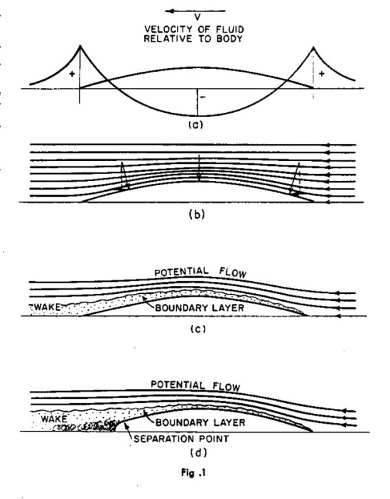
smoothly around the hull as shown in Figure 1(b). However, sea water is a real fluid with
finite viscosity, and no real hull is perfectly smooth. This results in the hull
"dragging" along a layer of water adjacent to it. This is called the boundary
layer, as shown in Figure 1(c). In addition, if there are strong discontinuities (such as
the hull tucking in too soon or a transom stern) then eddying may take place as shown in
Figure 1(d). The boundary layer grows in width from zero at the bow to some finite width
at the stern, and as a first approximation, it grows in width in proportion to its length
along the hull from the bow.
If sea water were
a perfect fluid with zero viscosity (or "stickiness") and if the ship's hull
were perfectly smooth, there would be no frictional resistance. The water would flow
smoothly around the hull as shown in Figure 1(b). However, sea water is a real fluid with
finite viscosity, and no real hull is perfectly smooth. This results in the hull
"dragging" along a layer of water adjacent to it. This is called the boundary
layer, as shown in Figure 1(c). In addition, if there are strong discontinuities (such as
the hull tucking in too soon or a transom stern) then eddying may take place as shown in
Figure 1(d). The boundary layer grows in width from zero at the bow to some finite width
at the stern, and as a first approximation, it grows in width in proportion to its length
along the hull from the bow.
Just how wide is the boundary layer at the stern? Well, that depends on the size of the vessel and its speed through the water. Figure 2 and Figure 3 are photographs I took in October, 1984, of the 1,500 ton Columbian frigate ANTIOQUIA (CM 53) during underway replenishment exercises (see Note 1 for some interesting "off topic" information regarding this vessel). She is moving at a speed of approximately 15 knots. Using the men on deck as a scale reference I estimate the width of the boundary layer at the transom is approximately 6 feet. Figure 4 is a view looking down at the amidships main deck of my ship, the 9,560 ton USS SOUTH CAROLINA (CGN 37) during the same exercise (see Note 2 for "off topic" information regarding this photograph). SOUTH CAROLINA is also moving at about 15 knots. Judging from the size of the men in the photograph, and the fact that the main deck amidships is about 25 feet above the water, I estimate the boundary layer is about 6-8 feet wide at this point, and probably twice that width at the stern.
| Click to Enlarge |
||
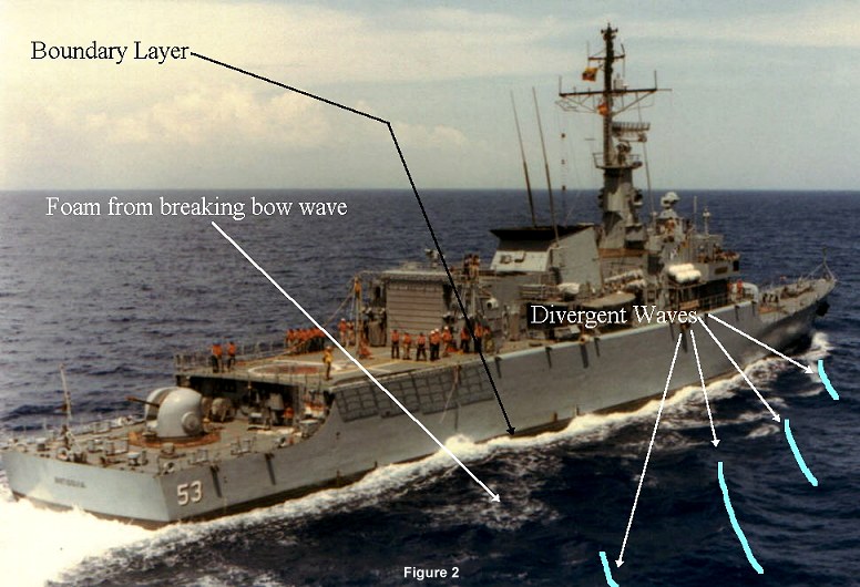 Figure 2 |
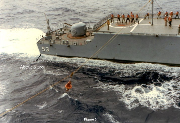 Figure 3 |
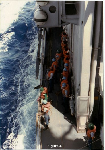 Figure 4 |
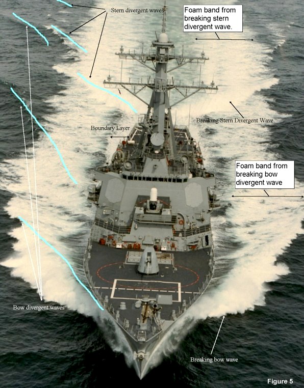
Figure 5 is a dramatic bow on view of 8,420 ton USS GONZALEZ (DDG 66) running full power trials off the coast of Maine. She is moving at 30+ knots. From this photo, and another stern on photo of the same sea trial that I have, the width of the boundary layer at the stern is about 25 feet. Don't confuse the boundary layer with the frothing remnants of the breaking bow wave which extend out about 75 feet from both sides of the vessel - more on this later.
Summing up, for modeling purposes we can say the following about any ship's boundary layer:
Click to Enlarge
 1.
If you are displaying your model at any speed above bare steerage way (say about 3-5
knots) you should model a frothing boundary layer next to the ship's hull.
1.
If you are displaying your model at any speed above bare steerage way (say about 3-5
knots) you should model a frothing boundary layer next to the ship's hull.
2. The boundary layer grows in width from zero at the bow to some finite width at the stern.
3. The width of the boundary layer is directly proportional to how far along the hull it has travelled (i.e., at amidships it's half the width at the stern).
4. The actual width and intensity of the boundary layer depends on the size and the speed of the vessel. Use the above examples as a guide, or consult overhead photographs if available.
Don't rush off just yet to paint that boundary layer alongside your model. The boundary layer will ride along the top of the transverse wave system that the vessel generates, which leads us to wave-making resistance.
WAVE-MAKING RESISTANCE
Any object moving through the water at the surface will create a disturbance in the water
surface which is manifested by a wave pattern. This wave pattern moves seemingly locked to
the ship creating it and it is a very significant, and at high speed it is the dominant,
portion of the ship's resistance. Through many years of analytical and experimental
research, the best description of this wave pattern has been found to be given by the
Kelvin wave pattern as shown in Figure 6 (Ship modelers, a hint: press your "I believe" button).
This pattern of waves consists of two types of waves. First, there are the divergent waves which start at the bow and stern, and angle aft. Note that the lines of the wave crests are not straight, they curve somewhat aft. Next, there are the transverse waves which are originally perpendicular to the ship's line of motion, although the further away from the ship they get the more they tend aft due to friction.
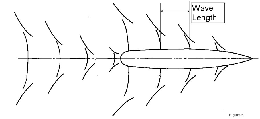
Note that a line originating at the bow, heading aft, and at an angle of 19.5 degrees (20 degrees is fine for modeling) to the ship's centerline, defines the intersection of all divergent and transverse wave crests. ALL displacement type surface ships, except those operating in very shallow (i.e., ship almost aground) or in very narrow channels, will make this type of wave pattern. It is for this reason that I am a bit dismayed to see a beautifully made ship model spoiled by a divergent bow wave coming off the bow at a 45 degree angle - real ships just don't make that sort of wave pattern. By the way, Figure 6 is drawn to scale and can be scaled up or down as necessary to suit the scale and desired "speed" of your model. Don't worry about the hull plan. Scale up the bow and stern Kelvin wave patterns and then position them at your model's bow and stern.
The next obvious question is "How much should Figure 6 be scaled?" That all depends on the speed you desire to display your model at. Principles of Naval Architecture (1967, Society of Naval Architects and Marine Engineers) gives a formula for the transverse wave length (crest to crest) based on ship's speed, but it then goes on to say that the transverse wave length is actually a little shorter in the vicinity of the ship. Assuming the wave length to be 90% of its open water length, a very good approximation to the transverse wave length is: Transverse Wave Length = ((Ship's Speed, Knots)^2)/2
|
Thus, the transverse wave lengths for a given ship speed are: Speed Wave Length 5 kts 13 feet 10 kts 50 feet 15 kts 113 feet 20 kts 200 feet 25 kts 313 feet 30 kts 450 feet 35 kts 613 feet |
Make sure you get this right. One of my first attempts to model a wake pattern was with an old 1:1200 scale Bachmann Miniships USS PENNSYLVANIA (BB 38) that I had bought for $1.00 back in the mid 1970's (my old, crude models become "experimental" ships!). Actually for a pre-assembled plastic "toy" it's quite good. Anyhow, the technical execution of the boundary layer and wave pattern looked good, but when whenever I looked at it I got the impression she was REALLY going fast. As I delved more into the subject I learned why - the transverse wave length corresponded to a speed of about 26 knots! Only in the wildest dreams of PENNSYLVANIA's chief engineer would she make 26 knots as she would need at least an additional 70% more installed horsepower to attain this speed.
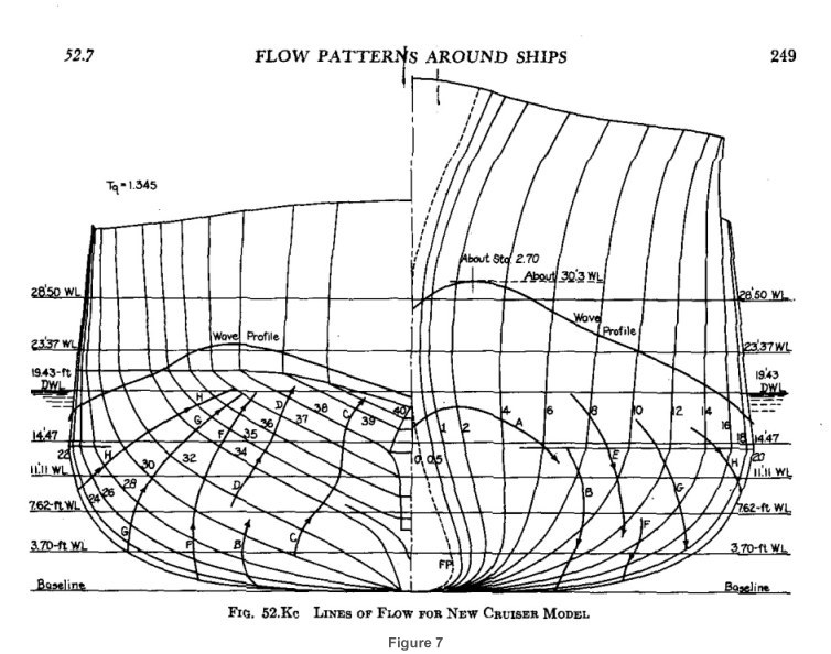
Just how high are the waves? Again, that depends on the speed and size of the vessel. At the bow the water is actually forced higher up along the ship's side than it will be when further away from the hull. This also causes the bow divergent wave to be the first wave to break. Figure 7 is plot of the wave pattern around a PORTLAND class CA at a speed of 32 knots. The bow wave is forced up about 12 feet above the at rest waterline, and it reaches its peak height about 40 feet aft of the stem. Amidships the transverse wave is actually 2.5 feet below the at rest waterline, building up to a height of about 5 feet above the at rest waterline at some 40 feet forward of the stern. The is a transverse wave with a wave length of approximately 500 feet and a height (trough to crest) of 7.5 feet. Refering again to Figure 2, ANTIOQUIA's divergent bow waves appear to be about 4-5 feet in height at the stem, and about 3 feet in height further out. This is purely an eyeball estimate. In Figure 5 GONZALEZ's divergent waves appear to be at least 6 feet in height,maybe more, further out from the ship. Another bow on photograph I have of USS COLE (DDG 67) running full power trials shows the bow wave forced up to nearly the top of the bow numerals (you can just make out the horizontal bar in the 7), some 18 feet above the at rest waterline.
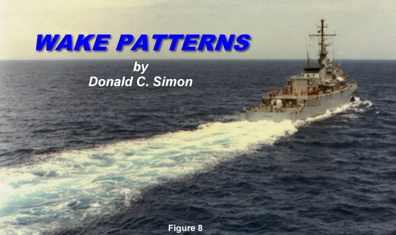
When the divergent waves grow enough in height they will start to break, just like breaking waves on the beach. Once the wave breaks the white foam pretty much stops in place and it appears to recede in a band parallel to the ship's side. The first divergent waves at the bow and stern are the most likely waves to break. In Figure 2 the divergent bow wave is just breaking and the foam extends out to maybe 15-20 feet from ANTIOQUIA's side. Due to the relatively low speed of ANTIOQUIA the foam band is rather patchy as it recedes alongside. At high speeds (Figure 5) both the bow and stern divergent waves break with great intensity. Here the foam recedes in nearly solid bands along GONZALEZ's sides, and it extends about 75 feet from the ship's sides. Note that there is an area between the boundary layer and the receding foam that is only partially covered with foam. At the stern the ship's prop wash churns up the boundary layer, so in the center there is a relatively homogenous area that is partially foam covered. The foam persist for quite some length behind the ship. In Figure 8 ANTIOQUIA's wake is still rather strong even a full ship length behind her, although she's only making about 15 knots. This also illustrates the difficulty in trying to conceal a moving vessel from aerial observation (that pesky water, if only it wouldn't foam...).
|
Summing up, for modeling purposes we can say the following about a ship's wave pattern: 1. A Kelvin wave system (see Figure 6) will be generated at the bow and stern. If the ship has a transom stern, split the stern Kelvin wave system down the middle and move the origins to the transom corners. 2. The length of the transverse waves (crest to crest) is proportional to the square of the ship's speed. 3. The wave at the bow will be forced up higher than the height it will have further out from the ship, in some cases approximately twice as high. 4. The wave immediately at the stern will be forced up higher due to the prop wash. 5. The foam generated by breaking waves will recede parallel to the ship's side in parallel bands. 6. The boundary layer will ride along the top of the transverse wave system. |
How much of this wake pattern should be displayed? That depends on how large a diorama you intend to make. Most waterline vessels are displayed on a "water" surface approximately 1-1/4 to 1-1/2 times as long as the ship by about 3 times as wide as the ship. With this size base you will definitely see the first divergent bow wave (of course), a bit of the second divergent bow wave and maybe a bit of the third. All of the boundary layer will be visible. The stern wave pattern and "Rooster Tail" should be shown as well. Those building very large dioramas (and I have seen several) should be prepared to model a very large wake pattern.
The actual technique of modeling the water is a topic for another day. One of the best techniques I have seen to date is that used by Mr Mike Taylor. He uses acrylic gel medium and gets great results (no, this is not a paid endorsement - I've never met him).
PARTING COMMENT
One final note. While it is visually very exciting to see a warship at maximum speed,
remember that warships spend about 90+ % percent of their underway time at cruising speed,
generally 12-18 knots. Why? As a first approximation, the amount of power required to
propel a ship is proportional to the cube of its speed. To go twice as fast requires EIGHT
times as much power. Since fuel is burnt at a rate directly proportional to power, this
also means you are burning your fuel at eight times the previous rate. Charging around the
ocean at 30 knots is a great way to quickly run out of fuel, and it's really embarrassing
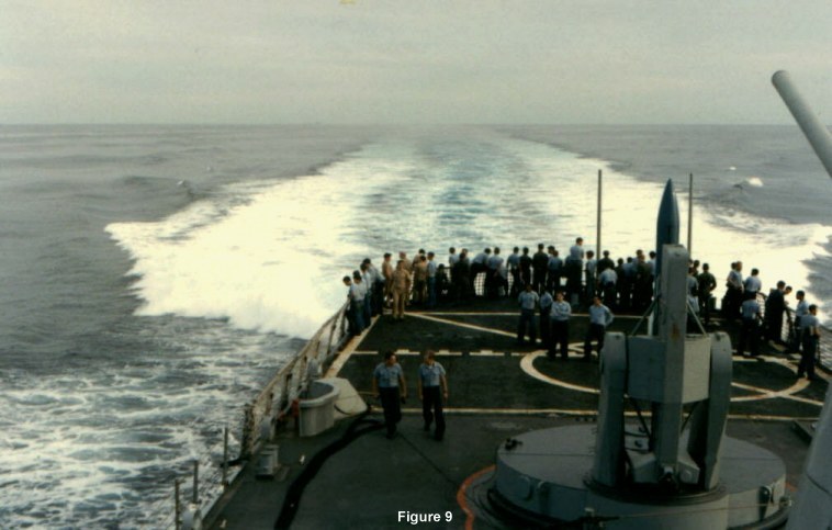
to have to grovel for a tow in mid ocean. Figure 9 was a rare opportunity for
me. The work day was over, I didn't have the watch as Engineer Officer of the Watch (EOOW)
in #2 plant, the seas were extremely calm, and SOUTH CAROLINA was doing a full power run.
Here she is kicking up an enormous wake . Note also how many officers, chief petty
officers and crewmen are gathered on the fantail to witness something they rarely get to
see. Notice also that the wake extends nearly to the horizon. As I took this photograph
from the 0-2 level (the height of eye is about 55 feet), the horizon is 8.5 miles away!
NOTES
Note 1. These pictures were taken during SOUTH
CAROLINA's 1984 post overhaul refresher training off Guantanamo Bay, Cuba (aka
"Gitmo"). While in port my friend, Max Mulholland, and I were treated to a tour
of ANTIOQUIA. This sharp 1,500 ton frigate was built by Howaldt Deutsches Werft (HDW),
Kiel, Germany, and had just been delivered to the Columbian Navy. The commissioning
Columbian officers and senior petty officers had been given extensive German language
lessons, but they didn't know too much English. Max is fluent in German and I can speak it
enough to get into trouble; neither of us can speak Spanish. So there we were, two US Navy
officers, aboard a Columbian frigate, conversing with their officers in German, at a US
Navy base, on the island of Cuba. Go figure...
Note 2. The photo was taken from the 0-3 level, amidships, looking down and forward at the port side. There are some interesting details to note in this photograph. From where the main deck meets the sheer strake (i.e., the uppermost plate in the side of the hull) to about 8 inches inboard, the deck is painted Haze Gray. At this point there is a vertical plate about 2-3 inches high. Outboard this plate is Haze Gray and inboard it is Deck Gray. The plate forms a sort of "gutter" to direct water to the scuppers. A scupper can be seen above the man standing at the rail with the green hard hat. Scuppers act as "downspouts" to direct water off the deck at intervals, and they are made of hard black rubber. Forward of the scupper is a boat boom in its stowed position. At the outboard end of the boom (here pointed aft) is a light. Further forward can be seen the steel wire topping lift with its turnbuckle. The topping lift supports the weight of the boom. Further forward, hidden behind the life raft containers, is the hinge pin that the boom pivots on. Years ago boat booms were tapered wood spars, well stained and varnished, but today they are square steel tube with Haze Gray on the sides and bottom, and non-skid on top. Boat booms are rigged out only when at anchor, NEVER while underway (the same applies to acommodation ladders). About 6 inches inboard of the "gutter" is bare steel deck painted Deck Gray. At this point the non-skid starts. Non-skid is mixed to match the color of Deck Gray paint but it's never a perfect match. The object with the white, 5 spoke handwheel is the shore steam connection. It's wrapped in insulation and painted Haze Gray. The square uptake with surrounding protective mesh is the auxilliary boiler uptake. CGN's were equipped with an oil fired "Scotch" boiler to generate service steam if the reactors were shut down and shore steam was not available. As I was M2 Division Officer at the time this piece of equipment was under my cognizance. To be honest both my nuclear trained machinist mates and I were scared to death of this thing and we called it the "auxilliary bomb."
